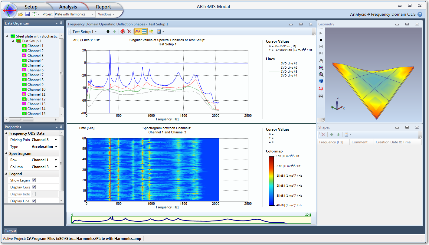
With the Frequency Domain Operating Deflection Shapes (FODS) editor you can display the deflection of the structure as a function of the frequency, see below. The media used for this replay is the project geometry. The animation will include any slave node equations that has been defined and all automatically generated interpolation motions. Just click on any Singular Value point in the top diagram to preview the Operating Deflection Shape at this frequency.
Storing Operating Deflection Shapes
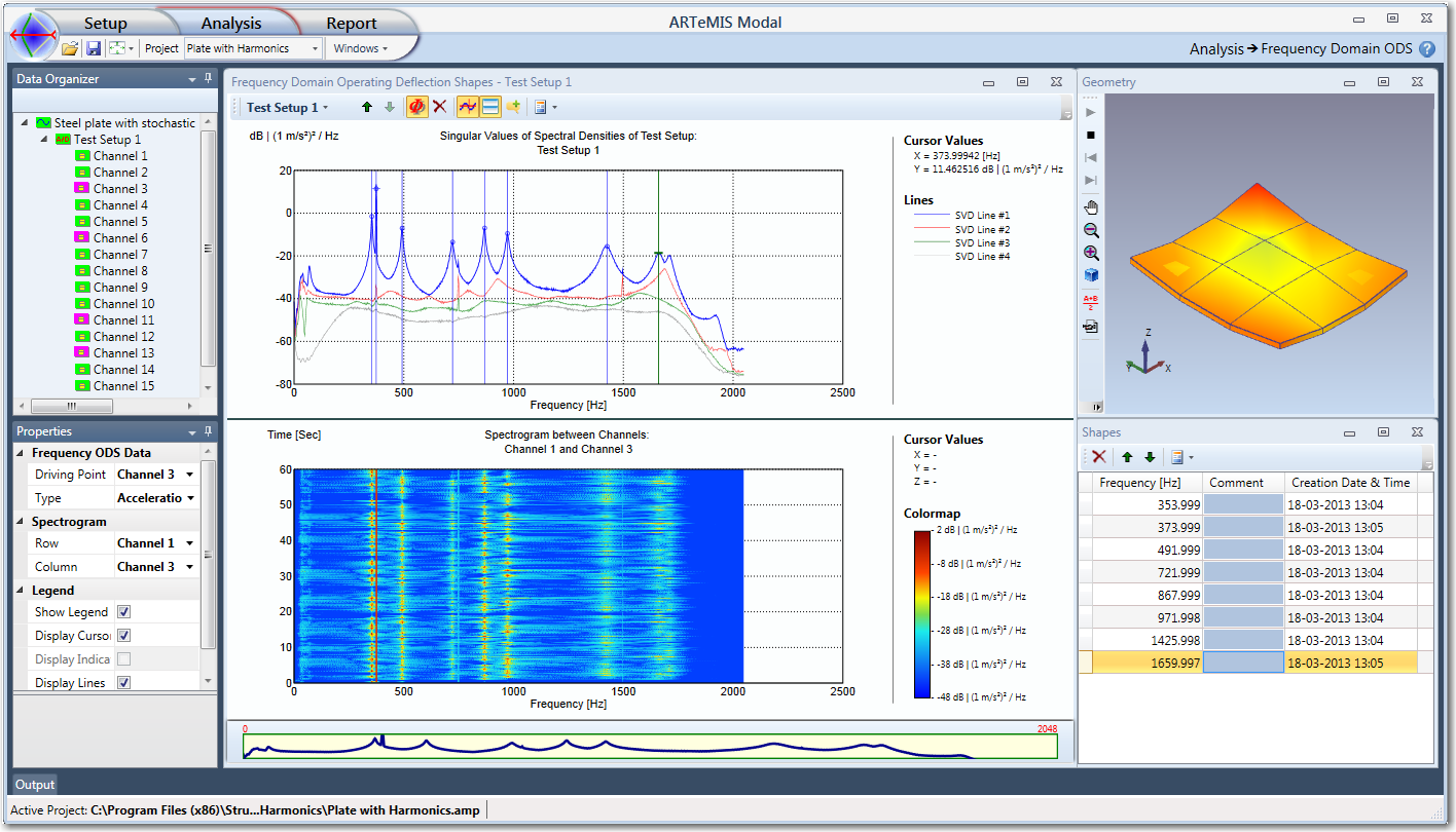
To store the Operating Deflection Shapes in a similar manner as modes click the Add New ODS button  . When double clicking in the top diagram the corresponding Operating Deflection Shapes are stored in the Shapes list to the right.
Driving Point Channel
The FODS editor needs to be informed about what type of data that has been uploaded to it. It is also necessary to know the initial unit of the data. This configuration of measurement types and units is performed in the Properties window. In order to display absolutely scaled deflection shapes at a certain frequency, it is necessary to be able to select the driving point channel, which is done in the Properties window as well, see above.
There are two ways to display the deflection of a structure in frequency domain; absolutely and relatively scaled.
Absolutely Scaled Deflection
The deflection of the structure can be absolutely scaled to a reference channel. In this case the deflection of the structure is adjusted, so that the movement of the point of the reference in the measurement direction is moving exactly what has been measured in the reference channel. To enable this you have to select a Test Setup in the Data Organizer and a Driving Point channel which is done in the Properties window in the section called Frequency ODS Data.
If only a single Test Setup exists in the project then, if enabled, all projection channels can be used as driving point channels and otherwise all channels in the single test setup can be used as a reference channel. If several Test Setups exist then only the actual reference sensors used during the measurement will be available as driving point channels.
Relatively Scaled Deflection
If you just want to see the shape of the deflection, like in the case of un-scaled mode shapes, you just select the Measurement Project item (top level) in the Data Organizer. In this case the maximum value of the deflection shape will be 1 and everything else relatively scaled to this value.
See Also